Thyristor Na Transistor Which Is Best for Microprocrssor
Q1 Q2 are NPN PNP transistor such that collector of Q1 connected to the base of Q2. Figure 2a shows the thyristor junction structure as a composite of a pnp transistor T1 and an npn transistor T2 by visualizing an imaginary plane through the pellet as shown by the broken line.

Variable Power Supply Circuit 0 50v At 3a With Pcb Eleccircuit Com Power Supply Circuit Voltage Regulator Electronic Circuit Projects
The top transistor conducts if its input the small dot is low the bottom transistor no dot if its input is high.

. Thyristors can operate at higher voltages and currents than transistors. The most simple gate is the NOT gate which inverts the input level. It specifies the maximum allowable non repetitive current the device can withstand.
When to Use Relays and Transistors. The thyristor is formed by four layers of semiconductor material in which P-type material and the N-type material is connected in an alternative manner while the transistor is formed by joining three layers of semiconductors. In its most basic form a thyristor has three terminals.
Full PDF Package Download Full PDF Package. Usage as an Amplifier. Power handling is better for thyristors because their ratings are given in.
If thats the case. Thyristors consist of four layers of semiconductors. The thyristor and transistor have the different designing procedure.
Figure AN10011 SCR Block Construction N P N P N Gate P Cathode J1 J2 J2 J3 Anode N N N Cathode Gate Anode Load P P Two-transistor Schematic Two-transistor Block Construction Equivalent Figure AN10012 Coupled Pair of. The diode will do its job whenever the gate triggered. Due to difference in fabrication and operation it is possible to have thyristors with higher voltage and current ratings.
Applying a positive voltage to the anode will not produce any significant current until the diodes threshold voltage is exceeded. The PNPN thyristor can be considered as two transistors Q1 Q2 connected in cascade mode. These little guys are the workhorses of most control circuits for small current applications.
Supposedly an SCRthyristor is just a simple four layer PNPN semiconductor. In the two-transistor equivalent circuit of a thyristor Figure 1b a positive trigger current IG can flow in the forward direction through the gate-cathode PN junction J3 and affect an injection of electrons from the N-cathode emitter of the NPN transistor. Thyristor is considered as tightly couple pair of transistors in analysis.
The gate controls the flow of current between the anode and cathode. Rating of a transistor is always in watts while that of a thyristor is in kWs ie. Silicon controlled rectifier SCR TRIAC gate turn off switch GTO silicon controlled switch SCS AC diode DIAC unijunction transistor UJT programmable unijunction transistor PUT.
A diode is a two-terminal device that exists anywhere p-type and n-type. THYRISTOR-BASED FACTS CONTROLLERS FOR ELECTRICAL TRANSMISSION SYSTEMS. Anode positive terminal cathode negative terminal and gate control terminal.
Dvdt rating of thyristor indicates maximum rate of rise of anode voltage that will not trigger the device without any gate signal. When a circuit calls for a SCRthyristor and there isnt one available can it. Thyristor SCR is a semiconductor device that performs the action of switching as well as rectification.
Capacitor C S acts as a short circuit so the voltage across SCR is zero. For very high or unknown loads a relay is your best and most practical option. Here the snubber circuit provides dvdt protection to the thyristor.
Before SCR is fired by gate pulse C S charges to full voltage Vs. Thyristor is a word formed by the merger of thyratron and transistor. Choose a transistor for smaller loads when power consumption is important or if you need to switch something millions or billions of times.
Unlike trying to make a transistor using two back-to-back diodes which doesnt work at all because of the need to have a very thin base region separating the collector from the emitter you can make an SCR using two discrete transistors but it will behave quite differently in many respects from an integrated one. Transistor is simplified as two diodes NPN when connected by Anodes and PNP when connected by Cathodes. Thyristor is a simple diode with a gate.
Bipolar transistors come in small packages can be driven by IO pins directly and are VERY cheap. Thyristors can be used as switches but not as amplifiers. The P-N-P-N structure of a thyristor is matched by the P-N-P and N-P-N structures of the bipolar transistors the base of each device being connected to the collector of the other device.
Semiconductors are directly adjoined to each other. When switch S is closed sudden voltage is applied to the circuit. For a specialized solution the additional devices outlined present further options.
Thyristors are a broad classification of bipolar-conducting semiconductor devices having four or more alternating N-P-N-P layers. Transistors can be used as switches or amplifiers. Youll commonly find through-hole parts in the 3-pin TO-92 style package.
Thyristor and transistor both possess three terminal but the three. Thyristor is a four-layer device while the transistor is a three-layer device. Thyristors having better power handling capacity.
It will stop only when its A-C goes below holding current. Thyristors can be used in circuits delivering larger amounts of power compared to transistors. Transistors are used to make logic gates as the lowest level building blocks.
Yes and no. There are two variants the NPN and PNP. 37 Full PDFs related to.
The operation of a PNPN device can best be visualized as a specially coupled pair of transistors as shown in Figure AN10012. As it exhibits the rectification action of thyratron as well as controllability as that of. 19 Turn ON Switching Two-Transistor Analogy The turn ON switching of a thyristor is best explained using the two- transistor analogy.
Didt rating of thyristor indicates maximum rate of rise of anode to cathode current. It is a 4 layer and 3 junction device formed by the combination of alternating p and n-type semiconductor material. The NOT gate is built with 2 transistors.
The gate terminal collector terminal of Q2 connected to the base of Q1. A thyristor is a four-layer device with alternating P-type and N-type semiconductors P-N-P-N. The primary function of a thyristor is.
Transistors consist of three layers of semiconductors. To ensure that this circuit behaves like a thyristor it is necessary to pick suitable parameter values of the NPN and PNP devices plus external resistors. As time passes voltage across C S builds up at a slow rate.
A logic 0 becomes a 1 and vice versa. A short summary of this paper. Diodes transistors and thyristors are all types of semiconductor devices.

Lm317 2n3055 3a Variable Power Supply Eleccircuit Com Power Supply Circuit Power Supply Design Electronics Projects

Transistor Circuit Diagram Using A1941 And C5198 Circuit Diagram Electronic Circuit Design Electronics Circuit

12 Volt Dc Motor Speed Controller How To Make Simple Diy Hacks Easy Way To Make Dc Voltage Controller 12 Volt Dc Mot Motor Speed Motor Electronics Basics

Pin On Circuit Diagram

What Is Thyristor Silicon Controlled Rectifier Scr Electronic Parts Control Electronic Engineering

One Transistor Relay Delay On Timer Circuit Electronic Circuit Design Electronics Circuit Circuit Projects

Temperature Sensing Circuit Using Thermistor Google Search
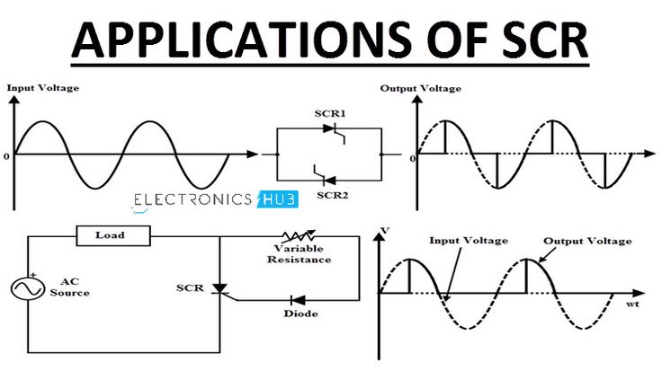
Scr Applications Switch Ac Dc Power Control Over Voltage Protec Power Dc Circuit Application

Transistor Construction Eletronica

Tyn612 Thyristor Pinout Electrical Diagram Company Letterhead Template Electrical Breakers

Conheca O Rele De Estado Solido Circuit Diagram Electronic Circuit Design Electronic Schematics
Tda2030 2 1 Amplifier Board Subwoofer Circuit Diagram Xtronic In 2022 Circuit Diagram Subwoofer Amplifier

Relay A Relays Is An Electrical Switch That Opens And Closes Under Control Of Another Electrical Circuit Electronica

Pin On تجارب

Lm338 Datasheet Adjustable Power Supply 5a And 10a Elec Circuit Electrical Circuit Diagram Power Supply Power Supply Circuit

Ayuda Como Puedo Bajar El Voltaje De 5v A 3v Voltage Regulator Electronic Circuit Projects Circuit Diagram

12v Auto Turn Off Battery Charger Electronics Area W 2019 Elektronika

Pin On Electronics Engineering

Single Transistor Audio Mixer Circuit Electronic Schematics Electronic Circuit Design Basic Electronic Circuits


Comments
Post a Comment